|
2. Getting started with Poses++ |
|
 Poses++ Project
Program a Poses++ Module
Check a Module
Build a Model
Simulate Model
Run modes and time warping
Network inspector
Breakpoints, Traces and Watches
Options
Simulation Results
Licence Viewer
Layout Editor
Animation Player
When you start Poses++ via posdesk.exe then the it's main window will pop up:
Poses++ - the first start
| 2.1. Poses++ Project |

|
A Poses++ project is a file typically with the extension .ppp and the directory where this file stored. The file itself contains plain text configuration informations.
Example:
To open an existing Poses++ project (f.i. one of the examples) you have to open the corresponding project file project.ppp.
Poses++ project contents
To create a new Poses++ project via File|New Project you have to select a directory - for example TestProject and you have to define the project file name - for example project.ppp.
Poses++ new project
In this project directory TestProject Poses++ will create the specified file project.ppp an will fill in the initial configuration informations. When you open the Poses++ editor firstly and no main Poses++ file is specified Poses++ will create a main model file TestProject.pos automatically.
| 2.2. Program a Poses++ Module |
|
The new project operation opens the text editor with the smallest correct Poses++ module automatically. Later you can open the editor by Model|Edit source or Tools|Text Editor.
Example:
The Poses++ file C:/Poses++ 2.0/examples/signal/signal.pos to edit the module signal will be created and opened automatically.
Poses++ file signal.pos with module signal
The editor is a typical plain text editor whith menus, short keys and popup entries.
Example: After editing the editor could look like below.
Edit a Poses++ module
You can edit Poses++ source files also with any other text editor. The Poses++ compiler - the next necessary tool in the chain of model building - is able to accept files from UNIX text editors too.
| 2.3. Check a Module |
|
You can check the syntactical correctness of a Poses++ file at any time, usually
you will do it untill your Poses++ file has a correct syntax.
You have to call Model|Syntax Check or the button with the image
 and
the Poses++ console will show informations such as the result of the check. If warnings or errors
occur then you can double click at these message lines in the console and
the focus will be switched to the editor in which the cursor shows the error
position.
and
the Poses++ console will show informations such as the result of the check. If warnings or errors
occur then you can double click at these message lines in the console and
the focus will be switched to the editor in which the cursor shows the error
position.
Example:
Syntax check for signal.pos
| 2.4. Build a Model |
|
In order to generate runable simulation models you must build a model library on the target host. You can find the entry field of target host under Model|Options|Server. Building a model library is a task of Poses++ daemon. The Poses++ compiler has to transform you model souce code into C++ source code and afterwards the selected C++ compiler will generate binary code which will be linked into dynamically loadable code in a model library.
Example:
If you call Model|Build for C:/Poses++ 2.0/examples/signal/signal.pos then the process will be reported to the integrated Poses++ console.
The Poses++ file signal.pos and all other necessary files from the project directory would be mirrored to the server side to a mirror directory [var]/[user]/C_/Poses++ 2.0/examples/signal if the simulation server is not able to access the project directory directly. This directory is created in the var directory (see also: Software components) for the user account you have on the machine which is your simulation server. In case of localhost the Poses++ server can access the project directory directly and so file mirroring to a remote machine is not necessary. After mirroring the Poses++ compiler creates from a Poses++ file a Code file called signal.cod. The C++ compiler compiles the code files and creates a model library libsignal.so or libsignal.dll on the target host. This model library contains the developed modules LIGHT and SIGNALIZATION now in binary format as runable simulation models.
| 2.5. Simulate Model |
|
In order to start a simulation session a correct model library for the current Poses++ project on the target host must exist.
When you start by Model|Simulate or the button with the image
 a Poses++ server will be started - a login
will follow - and the server will receive a request to load the
model library. All these operations are tasks
of the Poses++ daemon. After these steps an
inspector window will pop up.
a Poses++ server will be started - a login
will follow - and the server will receive a request to load the
model library. All these operations are tasks
of the Poses++ daemon. After these steps an
inspector window will pop up.
Example:
Poses++ experiment inspector
The parts of the panel in detail:
|
Reset of current simulation model. | ||||||||||
|
Starts or stops the execution of current simulation model. | ||||||||||
|
Switch to run an experiment faster within the simulation state RUN. During this mode the Panel of Experiment-Tool doesn't update all datas of experiment. | ||||||||||
| sec | Time unit of the model. It is the unit of the simulation server to interpret all time values in the model. | ||||||||||
|---|---|---|---|---|---|---|---|---|---|---|---|
| READY | An experiment has got always one of the following simulation
states:
|
||||||||||
| 0:19:20h | Current model time of simulation. |
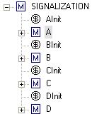
The hierarchy is the entry of each model navigation. Starting from top module you can reach all sub modules, all predicates, all transitions and their arcs. In our model is SIGNALIZATION the top module and A, B, C, ... are sub modules. AInit, BInit, CInit and DInit are places directly instanciated as member of our top module. All members are listed according to their creating order in Poses++ file. If the module tree is deeper as shown then a plus sign stands before this member name which allow to open the next hierarchy level.
Every module can contain parameter, predicates and transitions. Every predicate, transition or arc has properties which describe the actual model situation.
Poses++ token windows (from the example airport)
The Poses++ console lists all informations for testing or debugging purposes as well as all output of the simulation server such as breakpoints, traces, and concessions described in the next sections. For example a trace of the events TransStartFire and TransStopFire has been defined for all transitions. With a double click of a line in the console window you can select the corresponding model instance. With a right click popup menu you can read the source code.
| 2.6. Run modes and time warping |
|
 |
The Run menu allows to start and to stop a connected experiment. If you select Run the simulation server will start the execution of your model code and will not stop except the model reached a deadlock situation or you or any other client application simultaneously connected to that experiment ask to Stop. If the model is tested as well and you are about to gain simulation results the menu item Run speed will also start the experiment but will decrease the communication between the client and the simulation server to a minimum. |
But if you want to debug your model behaviour it is sometimes necessary to use the Fire step (F8) command. This command will request the simulation server to fire only one transition. Combined with traces and/or breakpoints you are able to follow the ongoing changes step by step. In some more complicated situations a fire step is too raw for debug purposes. Then it could help to use the Event step (F7) command.
The future event list will show you single events which will occure on the given time in future. What are single events ? When a rule (a transition) fulfilled their conditions (described by arcs) it will generate an event for each single operation to destroy data or to create new data at the actual time or later change data. If e.g. such a rule describes the operation to destroy one token at the actual time, to generate a token after the end of the fire time of the transition you will see 3 single events for this operations in the future event list. You can't access the contents of the internal event list from your model directly. All changes in that list of operations will be driven by the simulation server itself according to your model declarations.
To run the simulation experiment for a simulation time distance (Run for) or until a specific simulation time point is reached (Run to) you have to specify this parameter via Run options in the following dialog box.
When the simulation server will reach this time it will Stop the experiment execution automatically.
In the same dialog you can also specify the speed of the simulation experiment. In most cases you want to run the experiment at full speed. This for you have to setup the maximum speed value (the default setup) . The Poses++ simulation server includes a mechanism which we call time warping. This is a time algorithm useful to run the simulation experiments in relation to the real time. When the time warp factor is set to 1 the simulation server should run the experiment in real time (1sec in the simulation model should be calculated in 1sec real time). When you select to run the experiment on full speed the time warp factor is set to zero with the meaning "run event driven" so fast as possible. When you select any other factor you can reach a slow motion or a quick motion behaviour. This time algorithm is very important to use Poses++ for real time simulation e.g. to use the simulation environment as automation test platform to put other software or plants into operation or on the other hand to connect the simulation server with a virtual reality system (a client from the view of the Poses++ simulation server).
When the simulation experiment is started you can close the connection to the simulation server by exiting the experiment window. The following message box will ask you:
either to Close the experiment whereby the simulation server keeps running the experiment which you can reconnect later or to Destroy the experiment. Destroying the experiment will stop and kill the simulation server task. After closing an experiment an already running simulation server will be offered to be reconnected at the next try to start an experiment. Simulation server with more than one client connected simultaneously will inform all other clients.
| 2.7. Network inspector |
|
To get a network overview, to inspect all running Poses++ daemons, to connect or destroy running experiments and so on you can use the network inspector. The headlines Network and Experiments are buttons to switch the focus between both sides.
Poses++ console commands to established connections
| 2.8. Breakpoints, Traces and Watches |
|
The simulation server can send events under defined and requested circumstances. Such events offer further possibilities for observation and evaluation of the simulation model. Interpreted as breakpoint, trace and watch such events are usefull to validate and debug the running simulation experiment.
Breakpoints, traces, and watches are manipulated in the same way. Therefore the necessary actions are illustrated at the example of traces:
Display:
To display all traces call View|Traces & Breakpoints.and the trace listing appears:
Listing of all defined traces
With a double click over the column Active you can switch the event on or off. The same double click over the column Breakpoint will alternate between a trace or a breakpoint event.
Create:
To create a new trace or breakpoint entry call the popup menu either from the instance overview (1) or from the trace listing (2)
|
|
|
and the trace dialog appears:
You can select the instances in a hierarchy based dialog where you can hook the selected instances on the left side.
Watches are also collected in a grid. With View|Watches you will get the watch window shown.
| 2.9. Options |
|
When options are changed and not yet applied they are displayed in red color. When changed options are already applied but not yet saved to project file contents then they are displayed in green color.
| 2.9.1 Model Options |
|
Call Model|Options
Poses++ Options|Model
Main file: is the root file where the Poses++ compiler starts to compile. A default entry is generated automatically when a new Poses++ project is created. The file by itself can import other files.All imported modules from the view of this source file will be available as module types to be instanciated later as the simulation model.
Command file: If you want to initialize certain experiment
parameters just after model creation and before simulation start, then you can
write such initializations into a command file. A command file is a text file
containing commands directly sent to the simulation server. Thats why this commands
must use the client/server syntax between Poses++ components. F.i. a
command like: puttoken PredicatePath TokenValue will put a token
corresponding to TokenValue into the predicate specified by
PredicatePath. The simulation server supports a lot of commands
to change model parameters and to control and to observe the simulation process
as a client/server interface.
Layout file: If you want to use animation then enter the name of the file which contains (or will contain) the initial layout for the animation. This file is given the Layout Editor and the Animator will open the layout file automatically.
Model: is that Poses++ module which should be the main modelling instance. In case no module is selected a dialog will pop up.
The module which you select from the list will be instanciated as model.
Experiment: is the prefix of the experiment designation. If more than one experiment will conflict a unique number will be added.
Select experiment before simulate will show the Network Inspector first when you requested to start a simulation experiment. You can select either to start a new experiment or to connect an already running one.
List modules before open model will show you the list of available modules to be choosen to become a model on every experiment start.
| 2.9.2. Build Options |
|
Poses++ Options|Build
Include path is a semicolon separated list of paths which will be used as additional include paths for C++ compilation.
Library path is a semicolon separated list of paths which will be used as import paths for Poses++ compilation. This is the way how you can use model collections as libraries.
Mirror path is a semicolon separated list of additional paths with should be mirrored to server side in case mirroring is necessary.
Mirror mask is a list of file extensions which should be used when mirroring files from client to server side. User C++ files is a semicolon separated list of C/C++ source files which contain functions necessary for you model. The C++ compiler will compile them and the object code will be linked to you model library.
C++ options are compiler specific options or defines which you want to append during the C++ compilation of your user C++ files.
Linker options are compiler specific or system specific options or defines which you want to append during the linking stage for you model library.
compile user code for Debugger if this option is marked compiler specific options and defines will be appended automaticially to produce binary code suitable for the corresponding debugger. To debug the model you have to start it and then you can attach the debugger to the process (pospp).
Save all editor files before build: If marked then all files opend to edit in Poses++ editor will be saved before building the model or checking syntax.
Close model before build: If marked then just before building the binary model library in the actual project the corresponding connected models will be closed what means the client asks the server to unlink the binary model code to enable to overwrite it. Otherwise building a model currently opened on this or on another target host can lead to the message already in use. This means a library is opened by a server and overwriting this library is not allowed.
Open model after build: If marked then the models just closed before builing will be reopend after build automatically.
| 2.9.3 Server Options |
|
Poses++ Options|Server
Host is the machine with a running Poses++ daemon which is selected to be the simulation server. You can select a host from the list or you can enter a host name.
User is the account on this machine which should be used to login.
Platform is a combination of hardware and operation system.
Mirror root is the path on the server side where mirrored files and files for model building will be stored in sub directories.
Server timeout is the maximum time in seconds the simulation server will wait for response on the communication sockket. If this time is over the simulation server will close or reject this connection.
Client timeout is the maximum time in seconds the client side will wait for response of the simulation server. If this time is over you will get a message box with a question to continue or to close the connection.
| 2.9.4 C++ Compiler Options |
|
Poses++ Options|C++ Compiler
C++ Compiler You can select an identifier representing a C++ compiler. A C++ compiler is necessary to build from C++ source generated by the Poses++ compiler dynamic loadable binary code (*.so/*.dll). This binary code contains the functionality of Poses++ moduls and will be loaded by the Poses++ server if a client requests such a loading process. The offered compiler identifiers depent from the installed server packages on your server machine. To get a selection of C++ compilers you have to be connected to the Poses++ daemon first.Without a C++ compiler you are not able to build models (see: Hardware and Software Environment).
Binary path, Include path and Library path are directories necessary for the C++ compiler - in most cases found automatically by Poses++ daemon. If this try was not successful please enter the requested paths manually.
| 2.10. Simulation Results |
|
Most of the informations needed to evaluate a simulation experiments are available via the attributes of predicates, transitions or arcs. You can inspect these attributes in the Properties page directly or you can collect attributes to a watch list. Much more powerfull is the client/server command interface. With the command attributes you can get the same informations as in your watch list in one single command. The same you can also request from extern posconsole or any other connected client software you wrote.
| 2.11. Licence Viewer |
|
Call Configuration|Licence Viewer:
To get informations about occupied licence entries the licence view will show you details about available and already requested licence entries.
Poses++ licence entries are independent from the hardware and the operating system. They are parametrized to the MAC address of an ethernet card. Poses++ licence entries are necessary for a simulation server if the model size is bigger than a certain limit. If the largest amount of either the instanciated modules or the transitions or the predicates is higher than a licence limit the simulation server which loaded such a model for simulation experiments will request licence entries from the Poses++ licence daemon. On every machine which run a Poses++ daemon a Poses++ licence daemon will be started automatically. In case this licence daemon can find a properly configured licence file for this machine in .../etc/poses.lic it will serve this licence entries for valid requests. In other cases this licence daemon will route incoming requests to the parametrized licence server or if no licence server was set to another licence server which is reachable in the broadcast area of the local network. Please take a look into .../etc/poses.cfg for examples to set parameters for serving or routing licence daemons.
| 2.12. Layout Editor |
|
You have to start the layout editor to desgin a layout. A layout consists of graphical objects and their properties.
Poses++ provides a functional interface described in the appendix. You can use all these functions of animation within the action body of a transition or within user modules. Most functions are also available as properties in the options dialog of the layout editor, especially options for width, text, position, edge color or face color.
A most important property of each layout object is the tag. A layout object never gets a name itself. But if you will animate it with an animation function then you must assign a tag at first. A tag is an alias name for one or more layout objects. Therefore you can identify one or more such objects by use the corresponding tag. But to build anyone associations you can give every layout object a list of tags also given to other objects.
Example:
highway.lay is the layout file for the Poses++ project signal. You can see the selected circle with the tag Bgreen.
The layout file highway.lay shows four traffic lights. In the simulation model they are distinguished A, B, C, and D. And in the layout file all important layout objects should be assigned to a tag.
for light A: the upper circle with the tag Ared,
the middle circle with the tag Ayellow, and
the lower circle with the tag Agreen.
...
for light D: the upper circle with the tag Dred,
the middle circle with the tag Dyellow, and
the lower circle with the tag Dgreen.
In order to animate this layout you can use the tags to change positions, change colors, and so on. To switch such as the light color you are describe:

 Pos_AnimFace("C"+"yellow", 1, 1, 0);
            //set face color (RGB code) of tag "Cyellow" on yellow.

 Pos_AnimFace("Cred"      , 1, 0, 0);
            //set face color (RGB code) of tag "Cred" on red.

 Pos_AnimFace("Cgreen"    , 0, 1, 0);
            //set face color (RGB code) of tag "Cgreen" on green.

The layout files contain text informations which describe the layout. Details you can find at Layout and animation command syntax.
| 2.13. Animation Player |
|
You can start the animation player to observe the model under condition that a layout file was designed by the Layout editor and also a simulation model includes animation functions. The tag parameter of these function calls refer to known tags within the layout file. That is such a tag refers to one or more layout objects. All changes, shifts or other updates of tags refer to these objects and result in an animation scene.
In order to observe the model by animation you must open one or more cameras as different views to the same layout. To control the play sequence of animation you can used the following dialog controls:
If the show each step is marked then all animation data will be shown in single steps good to follow step by step for debugging purposes.
Please be careful when you mark model synchron. If marked the animation player will stop the simulation server delivering animation commands so long until all received commands are processed and shown. This can brake or even stop the simulation server at times. But when your simulation server runs in real time with time warp factor = 1 you should avoid synchronization.
|
|